DescriptionFeaturesSPECIFICATIONSMODULE DIMENSIONSDatasheet PDF DownloadKVR16LS11/4 FAQ
There is no disadvantage (except possibly price) in using 1N4005 diodes for everything. The LED driver is powered using a 36V 2.5A SMPS. Is it possible to return a rental car in a different country? http://www.comchiptech.com/cms/UserFiles/QW-BG013%201N4001%20Thru456224.%201N4007%20REV.A.pdf, http://www.mccsemi.com/up_pdf/1N4001-1N4007(DO-41).pdf, http://www.vishay.com/docs/88504/1n4001gp.pdf, http://www.onsemi.com/pub/Collateral/1N4001-D.PDF. The current flows through the LED, and it illuminates. RL106F : Fast Recovery Rectifier. Or, if you prefer, if in doubt use decoupling capacitors. The voltage across a diode (any diode) while conducting is not something that is applied externally by the circuit it is in, it is a characteristic of the diode. Leo.. Wawa: This method of driving the 555 timer produces a square wave with an equal mark-space ratio. I can hardly believe that diode's manufacturers just throw away poorly performing diodes and do not try to sell them as a less tolerant device. I didn't want to say this only for someone to explain how to use a FET in place of a diode. My answer remains what it was, everything needs decoupling capacitors. Shouldn't this be a permanent connection. As we increase the applied reverse voltage, the electric field across the junction increases. That answers the question that I created the thread for. voltage the last 1n400x 2n400x are the number designated as reverse  Therefore, it can be used for the conversion of alternating current to direct current. That's why I gave you the reverse voltage because the reverse voltage is the only voltage you need to consider in the context of a question about a diode's ability to handle an applied voltage. That's a good idea. 10pF vs. 15pF at -10V). as a TO220 package so can be easily heat-sinked and finding one rated for 30A or more is quite possible. My guess is that years ago, when these diodes were just introduced and the semiconductor processes were not mature, the differences between different diodes were more pronounce. Leo.. Without the circuit diagram that you didn't post it's impossible to be more precise. When this applied input voltage becomes greater than 0.6 volts, IN4007 diode acts as a short circuit. When the law was passed and impemented and why. *A[-vP9 I had a feeling you would like it. Commentdocument.getElementById("comment").setAttribute("id","a3ef7d050c0c9636eb91040e58ad8232");document.getElementById("c0eb03b5bb").setAttribute("id","comment"); Notify me of follow-up comments by email. Case: Molded plastic Epoxy: Device has UL flammability classification 94V-O Lead: MIL-STD-202E method 208C guaranteed Mounting position: Any Weight: 0.33 gram. Would satellites going into a rendez-vous show a difference in potential leading to an arc between the structures? It looks like 1N4007 is the super version of all other 1N400x diodes. The second type is a PIN construction and is used for 1N4006 and 1N4007.
  The input side doesn't see the PWM so much as the converter has internal decoupling, but a schottky diode is very fast anyway. 8_5 +f`_R 6 F (a`,e0 W
During reverse biasing a leakage current flows through a diode which is negligible compared to forward current. I meant the max voltage the diode can tolerate when conducting. What is the breakdown voltage of 1N4001 diode? Zener diodes constantly work in this mode. Copyright 2022 by NetSonic. The given proteus simulation is the perfect example of the switching concept of the diode: The two circuits represent the states of the diode.
The input side doesn't see the PWM so much as the converter has internal decoupling, but a schottky diode is very fast anyway. 8_5 +f`_R 6 F (a`,e0 W
During reverse biasing a leakage current flows through a diode which is negligible compared to forward current. I meant the max voltage the diode can tolerate when conducting. What is the breakdown voltage of 1N4001 diode? Zener diodes constantly work in this mode. Copyright 2022 by NetSonic. The given proteus simulation is the perfect example of the switching concept of the diode: The two circuits represent the states of the diode. 
 As has been pointed out its the current or power rating you should be concerned with - using a schottky Therefore, you should use it for low frequency applications only. Fundamental difference between DC IV measured current leakage and AC CV measured conductance, Question about diode strings in high voltage applications. Pls learn their differences clearly by comparing datasheet, pinout, and applications before you choose for a replacement. Catalog
Are Germanium Zener diodes still obtainable? The arduino and LED driver are common grounded via another screw terminal.
As has been pointed out its the current or power rating you should be concerned with - using a schottky Therefore, you should use it for low frequency applications only. Fundamental difference between DC IV measured current leakage and AC CV measured conductance, Question about diode strings in high voltage applications. Pls learn their differences clearly by comparing datasheet, pinout, and applications before you choose for a replacement. Catalog
Are Germanium Zener diodes still obtainable? The arduino and LED driver are common grounded via another screw terminal. 
 On the Data sheet it is shown as 'Maximum repetitive peak reverse voltage'. Provide a diagram. The 1N4007 is a used general-purpose diode. Breakdown itself does not damage a diode, if the current is limited. I think there is some binning going on, but that is not all. What is the difference between 1N4001 and 1N4007 other than their maximum reverse voltage? Can someone put you on tv without your consent? What is the breakdown voltage of diode 1n4001 and 1n4007? If it was really just the doping densities and depletion layer width, I'd expect junction capacitance to vary as \$\propto \frac {1}{V_B}\$. Email:[email protected], 1N4007 Diode: Pinout, Equivalent, Applications [FAQ]. It is a diode of the 1N400x series in which there are also other similar diodes from 1N4001 to 1N4007 and the only difference between them is the maximum repetitive reverse voltage. Electrical Engineering Stack Exchange is a question and answer site for electronics and electrical engineering professionals, students, and enthusiasts. Additionally, sometimes (not very often) there are schematics where the diode works in avalanche breakdown mode, so you will need the breakdown voltage to be predictable. There appears to be two fundamentally different types of diodes sold as 1N4001..1N4007. I am concerned that the diode won't be fast enough for switching the PWM at the output side(I am using an arduino Uno for the PWM). I will just have to find a schottky diode in TO-220 package with a low reverse leakage current at a good price(I would only need 3A current rating max). Also because these drivers and LEDs are expensive and hard to get where I live. Contact US
It's just a screw terminal for input, a screw terminal for output, and another one for PWM pin. You should remember that the negative point of the resistor (bottom node) is not the same as the -ve node of the 220V sine source. voltage potential 1n4001 isis the lowest voltage. -ve carriers and the current always leaves from a cathode terminal. 468). 586 0 obj
<>/Filter/FlateDecode/ID[<401DF6FFA272F24CB132E6ECAAE4085F>]/Index[570 39]/Info 569 0 R/Length 86/Prev 96814/Root 571 0 R/Size 609/Type/XRef/W[1 2 1]>>stream
+ve carries terminal and current always flows into the anode. 0.6V is a forward drop voltage of 1N4007. Some diodes -- such as the 1N4001 -- will break down at 50 volts or less. However, you need to know functions of every pins before it can work better for you. 608 0 obj
<>stream
1N4007 can be used in variety of circuits, it is normally built for general purpose rectification purpose but it can also be used in any circuit where there is need of voltage blocking, blocking voltage spikes etc. In the final build I will use a Nano and a buck converter module that will step down the 36V to 5V, and feed the output to the Nanos mini usb. I would just draw a big red + and a big black - on the board with permanent marker pens. I did not mean reverse voltage. rectifiers are very common they start at 50v to 1000v breakdown How does JWST position itself to see resolve exact target? The best answers are voted up and rise to the top, Start here for a quick overview of the site, Detailed answers to any questions you might have, Discuss the workings and policies of this site, Learn more about Stack Overflow the company. The resistor value is chosen to limit the current that flows through the diode.
On the Data sheet it is shown as 'Maximum repetitive peak reverse voltage'. Provide a diagram. The 1N4007 is a used general-purpose diode. Breakdown itself does not damage a diode, if the current is limited. I think there is some binning going on, but that is not all. What is the difference between 1N4001 and 1N4007 other than their maximum reverse voltage? Can someone put you on tv without your consent? What is the breakdown voltage of diode 1n4001 and 1n4007? If it was really just the doping densities and depletion layer width, I'd expect junction capacitance to vary as \$\propto \frac {1}{V_B}\$. Email:[email protected], 1N4007 Diode: Pinout, Equivalent, Applications [FAQ]. It is a diode of the 1N400x series in which there are also other similar diodes from 1N4001 to 1N4007 and the only difference between them is the maximum repetitive reverse voltage. Electrical Engineering Stack Exchange is a question and answer site for electronics and electrical engineering professionals, students, and enthusiasts. Additionally, sometimes (not very often) there are schematics where the diode works in avalanche breakdown mode, so you will need the breakdown voltage to be predictable. There appears to be two fundamentally different types of diodes sold as 1N4001..1N4007. I am concerned that the diode won't be fast enough for switching the PWM at the output side(I am using an arduino Uno for the PWM). I will just have to find a schottky diode in TO-220 package with a low reverse leakage current at a good price(I would only need 3A current rating max). Also because these drivers and LEDs are expensive and hard to get where I live. Contact US
It's just a screw terminal for input, a screw terminal for output, and another one for PWM pin. You should remember that the negative point of the resistor (bottom node) is not the same as the -ve node of the 220V sine source. voltage potential 1n4001 isis the lowest voltage. -ve carriers and the current always leaves from a cathode terminal. 468). 586 0 obj
<>/Filter/FlateDecode/ID[<401DF6FFA272F24CB132E6ECAAE4085F>]/Index[570 39]/Info 569 0 R/Length 86/Prev 96814/Root 571 0 R/Size 609/Type/XRef/W[1 2 1]>>stream
+ve carries terminal and current always flows into the anode. 0.6V is a forward drop voltage of 1N4007. Some diodes -- such as the 1N4001 -- will break down at 50 volts or less. However, you need to know functions of every pins before it can work better for you. 608 0 obj
<>stream
1N4007 can be used in variety of circuits, it is normally built for general purpose rectification purpose but it can also be used in any circuit where there is need of voltage blocking, blocking voltage spikes etc. In the final build I will use a Nano and a buck converter module that will step down the 36V to 5V, and feed the output to the Nanos mini usb. I would just draw a big red + and a big black - on the board with permanent marker pens. I did not mean reverse voltage. rectifiers are very common they start at 50v to 1000v breakdown How does JWST position itself to see resolve exact target? The best answers are voted up and rise to the top, Start here for a quick overview of the site, Detailed answers to any questions you might have, Discuss the workings and policies of this site, Learn more about Stack Overflow the company. The resistor value is chosen to limit the current that flows through the diode.  HW$
W@d
j>,ZjwD0+L2w_r7w_~7w_St7o?/.%{r_SMTkm$JQK.-qtgKWIrk}cw
_znbg#Sl e7~PW>RZskzjV;z7F}bRFl':(Opn3e(?\<88o},:NMO,
{4Xc:rvNB]! The portion with the diode is the input side. What this means is that when their reverse breakdown voltage is exceeded, they will start to conduct current. I didn't answer about using a P-FET because as far as I know there is no way to use a FET as a diode. hbbd``b`${A $@v@A,7k The extra terminals are for future use. The maximum current carrying capacity is 1A and it withstands peak up to 30A. 2N7002ET1G Transistor: Pinout, Datasheet, Equivalent. A 1N4007 are specified to withstand 1000V DC, and will normally breakdown at a voltage of 1200V to 1500V, some up to 2100V. 2017-2022 Apogeeweb
It acts as a one-way switch that allows the current to flow in one direction and halts in the other direction. Do not operate and store at a temperature below -55 centigrade and above +175 centigrade. Learn about Zener diodes and build your own tester. That's going to drop efficiency of that driver. This is the minimum value for the resistor. diode is a much better idea if heat dissipation is an issue, and better still a lot of schottkys are available 2022 Community Moderator Election Results. Also, can I use a P-FET instead? The cathode is marked on the body of a diode by a band. What model Arduino? Due to process variations, manufactured semiconductor devices may have different characteristics. The 1N4007 diode is a standard recovery rectifier with a molded plastic case. Makes sense, not something I would have thought of. Extra ones won't do any harm and they don't cost much. endstream
endobj
571 0 obj
<>/Metadata 18 0 R/Pages 568 0 R/StructTreeRoot 39 0 R/Type/Catalog>>
endobj
572 0 obj
<>/MediaBox[0 0 612 792]/Parent 568 0 R/Resources<>/Font<>/ProcSet[/PDF/Text/ImageC]/XObject<>>>/Rotate 0/StructParents 0/Tabs/S/Type/Page>>
endobj
573 0 obj
<>stream
What are the possible attributes of aluminum-based blood? =2dvz?0Q;(8I2=jRw.sD\V*]pl.6.1C3-@e}M+PMSEnS'pa1 E}J# @jMBp 0SKWQh(9lH6f`'Jq a L ]'_Cbnqnz.uEzb.We<=&":SxUTmSQ-m"LH.|Xg-?CfbZM $m7xJ!#;zUFW~XS%i$TpP%,4q0Tp. Many manufacturers employ "binning" strategy for manufactured parts: they test the parts and divide them between several "bins" based on devices' performance. Thankfully, it did not blow up. Edit: I had a brainfart and labelled the diode as IN4007. In modern times we would likely use a different type of diode at higher frequencies (over a few kHz square wave or maybe 5kHz sine wave) so the differences are no longer that important, but a few folks have pushed the PIN types into RF service. Hi, Announcing the Stacks Editor Beta release!
HW$
W@d
j>,ZjwD0+L2w_r7w_~7w_St7o?/.%{r_SMTkm$JQK.-qtgKWIrk}cw
_znbg#Sl e7~PW>RZskzjV;z7F}bRFl':(Opn3e(?\<88o},:NMO,
{4Xc:rvNB]! The portion with the diode is the input side. What this means is that when their reverse breakdown voltage is exceeded, they will start to conduct current. I didn't answer about using a P-FET because as far as I know there is no way to use a FET as a diode. hbbd``b`${A $@v@A,7k The extra terminals are for future use. The maximum current carrying capacity is 1A and it withstands peak up to 30A. 2N7002ET1G Transistor: Pinout, Datasheet, Equivalent. A 1N4007 are specified to withstand 1000V DC, and will normally breakdown at a voltage of 1200V to 1500V, some up to 2100V. 2017-2022 Apogeeweb
It acts as a one-way switch that allows the current to flow in one direction and halts in the other direction. Do not operate and store at a temperature below -55 centigrade and above +175 centigrade. Learn about Zener diodes and build your own tester. That's going to drop efficiency of that driver. This is the minimum value for the resistor. diode is a much better idea if heat dissipation is an issue, and better still a lot of schottkys are available 2022 Community Moderator Election Results. Also, can I use a P-FET instead? The cathode is marked on the body of a diode by a band. What model Arduino? Due to process variations, manufactured semiconductor devices may have different characteristics. The 1N4007 diode is a standard recovery rectifier with a molded plastic case. Makes sense, not something I would have thought of. Extra ones won't do any harm and they don't cost much. endstream
endobj
571 0 obj
<>/Metadata 18 0 R/Pages 568 0 R/StructTreeRoot 39 0 R/Type/Catalog>>
endobj
572 0 obj
<>/MediaBox[0 0 612 792]/Parent 568 0 R/Resources<>/Font<>/ProcSet[/PDF/Text/ImageC]/XObject<>>>/Rotate 0/StructParents 0/Tabs/S/Type/Page>>
endobj
573 0 obj
<>stream
What are the possible attributes of aluminum-based blood? =2dvz?0Q;(8I2=jRw.sD\V*]pl.6.1C3-@e}M+PMSEnS'pa1 E}J# @jMBp 0SKWQh(9lH6f`'Jq a L ]'_Cbnqnz.uEzb.We<=&":SxUTmSQ-m"LH.|Xg-?CfbZM $m7xJ!#;zUFW~XS%i$TpP%,4q0Tp. Many manufacturers employ "binning" strategy for manufactured parts: they test the parts and divide them between several "bins" based on devices' performance. Thankfully, it did not blow up. Edit: I had a brainfart and labelled the diode as IN4007. In modern times we would likely use a different type of diode at higher frequencies (over a few kHz square wave or maybe 5kHz sine wave) so the differences are no longer that important, but a few folks have pushed the PIN types into RF service. Hi, Announcing the Stacks Editor Beta release!  The1N4007belongs to a sort of 1 A general-purpose silicon rectifier diode, commonly used in AC adapters for common household appliances. Calculating length of curve based on data points? MarkT: Enter your email address to subscribe to this blog and receive notifications of new posts by email. endstream
endobj
574 0 obj
<>stream
Your email address will not be published. RMS Reverse Voltage of 1N4001 is 35V while that of 1N4007 is 700V. My silicone mold got moldy. What happens to a diode once it reaches the breakdown voltage? Note: You may not be used to seeing the 555 wired the way it is.
The1N4007belongs to a sort of 1 A general-purpose silicon rectifier diode, commonly used in AC adapters for common household appliances. Calculating length of curve based on data points? MarkT: Enter your email address to subscribe to this blog and receive notifications of new posts by email. endstream
endobj
574 0 obj
<>stream
Your email address will not be published. RMS Reverse Voltage of 1N4001 is 35V while that of 1N4007 is 700V. My silicone mold got moldy. What happens to a diode once it reaches the breakdown voltage? Note: You may not be used to seeing the 555 wired the way it is.  The given proteus simulation is the perfect example of the switching concept of the diode: The two circuits represent the states of the diode. 1N4007 is a PN junction rectifier diode. PN diodes can be much more complex than a simple 2D model demonstrated in all the theoretical examples Can you provide any reference for your answer? For capacitive load, derate current by 20%. As reverse voltage is applied to this rectifier it will at some They also have lower junction capacitance at all reverse bias voltages (eg. One has to wonder if some parts are not even binned these days, but merely labelled as demand dictates, and propagated simply because they are foundational parts that will probably never go obsolete. When the voltage at the anode is higher than the cathode voltage, the diode is said to be forward-biased, since the electrical current is moving forward.. They have a large voltage drop when wired in their reverse direction.
  The driver and arduino are commond grounded to make the PWM work. As has been pointed out its the current or power rating you should be concerned with - using a schottky Regardless, I am humbled. What rating point advantage does playing White equate to?
  [^3@6@U= ;P |p;7'U`V 3*Dz8 7%DAcW8 )yJ r. Copyright 2013-2022 So how would it cope with its nominal rating of 1 Amp? Everything needs decoupling capacitors. Voltage may be present in the circuit due to charged capacitors. 1N4007 in Forward and Reverse Biased Mode When the input voltage applied to the anode terminal is +ve as compared to the cathode terminal, the diode is said to be forward-biased. There are applications which require more precision though. Please dont worry about not being good at drawing, no one minds that. Because I get careless and have blown a few things due to connecting them the wrong way. When a Zener diode under test (zut) is placed across the output, the Zener will conduct at its breakdown voltage and the volt meter will display this voltage. Because it is constructed with P and N-type materials. Diodes with higher reverse voltage ratings are intentionally manufactured with lighter doping so that the depletion region for a given reverse voltage is wider than it otherwise would be. Meaning of 'glass that's with canary lined'? 10 s, per JESD 22-B106. The maximum reverse voltage of a 1N4007 is 1000V.
  In this way, the diodes anode is at a higher potential than the cathode, due to which the current can surpass its depletion region. That seems like a reasonable approach to me, try it. As far as I see, all of their properties are same other than their maximum reverse voltages. It is many times more than the voltage used to energise it. Max Average Forward Rectified Current 1.0A at Ta=55degC. If you are planning to use them for something more sensitive, you might want to test them all to see which one suites better. So, you can use a 1N4007 for all of your applications, but your circuit efficiency will be slightly higher if you use a more appropriately-rated diode in low-voltage applications. Some diodes such as the 1N4001 will break down at 50 volts or less. Sorry to be a pain Nova_IN but please can you upload the drawings to this site, not provide a link to somewhere else. To obtain the maximum operating time of the diode, it is recommended to always stay between 30 and 40 V below its maximum repetitive reverse voltage and other values. Let me know if I'm wrong. The current which flows from anode to a cathode terminal is known as a forward current. Reverse biasing will restrict the flow of current and can damage the device if voltage applied is greater than reverse breakdown voltage. I am assuming you have a rectifier + filter connected to the mains supply and you have a resistor divider to measure the voltage. In a boost circuit, we only want the positive voltages to charge up a capacitor. Use 7-10 LEDs in series, or drop the supply to ~15volt. It allows current flow through only one direction that means current can flow from the anode to the cathode only and never from the cathode to the anode it likes a one way valve. endstream
endobj
startxref
So we can use this diode in circuits that are designed for less than 1A. 1N4148, 1N4733A, 1N5408, 1N5822, Zener Diodes. Heres a video explaining it - link. It is fairly low-speed rectifier diode, being inefficient for square waves of more than 15 kHz. Use 7-10 LEDs in series, or drop the supply to ~15volt. For actual curves illustrating the difference, refer to the Motorola Semiconductor Library databooks. A similar process happens for each of the diodes and the input voltage gradually decreases from 9 Volts to the required 3 Volts and can be used for the operation of any electronic equipment with a need of ~ 3V. For a better experience, please enable JavaScript in your browser before proceeding. The yellow wire is the PWM signal wire. This electric field exerts a force on the electrons at the junction and frees them from covalent bonds.
In this way, the diodes anode is at a higher potential than the cathode, due to which the current can surpass its depletion region. That seems like a reasonable approach to me, try it. As far as I see, all of their properties are same other than their maximum reverse voltages. It is many times more than the voltage used to energise it. Max Average Forward Rectified Current 1.0A at Ta=55degC. If you are planning to use them for something more sensitive, you might want to test them all to see which one suites better. So, you can use a 1N4007 for all of your applications, but your circuit efficiency will be slightly higher if you use a more appropriately-rated diode in low-voltage applications. Some diodes such as the 1N4001 will break down at 50 volts or less. Sorry to be a pain Nova_IN but please can you upload the drawings to this site, not provide a link to somewhere else. To obtain the maximum operating time of the diode, it is recommended to always stay between 30 and 40 V below its maximum repetitive reverse voltage and other values. Let me know if I'm wrong. The current which flows from anode to a cathode terminal is known as a forward current. Reverse biasing will restrict the flow of current and can damage the device if voltage applied is greater than reverse breakdown voltage. I am assuming you have a rectifier + filter connected to the mains supply and you have a resistor divider to measure the voltage. In a boost circuit, we only want the positive voltages to charge up a capacitor. Use 7-10 LEDs in series, or drop the supply to ~15volt. It allows current flow through only one direction that means current can flow from the anode to the cathode only and never from the cathode to the anode it likes a one way valve. endstream
endobj
startxref
So we can use this diode in circuits that are designed for less than 1A. 1N4148, 1N4733A, 1N5408, 1N5822, Zener Diodes. Heres a video explaining it - link. It is fairly low-speed rectifier diode, being inefficient for square waves of more than 15 kHz. Use 7-10 LEDs in series, or drop the supply to ~15volt. For actual curves illustrating the difference, refer to the Motorola Semiconductor Library databooks. A similar process happens for each of the diodes and the input voltage gradually decreases from 9 Volts to the required 3 Volts and can be used for the operation of any electronic equipment with a need of ~ 3V. For a better experience, please enable JavaScript in your browser before proceeding. The yellow wire is the PWM signal wire. This electric field exerts a force on the electrons at the junction and frees them from covalent bonds.  An old 19volt laptop supply is perfect for strings of 3-5 LEDs. It is a common practice not only for diodes. The 1n4007 diodes are a lot bulkier than the 1n4001 if I remember correctly +1 for "semiconductor processes were not mature". The reverse current is 5uA which is negligible. When this applied input voltage becomes greater than 0.6 volts, IN4007 diode acts as a short circuit. The power dissipation of this diode is 3W. %%EOF
I try to look for it in the datasheet but I don't know which parameter I am supposed to look at. The 1N4007 can withstand a higher reverse voltage(Vr), 1000V vs. (The 1N4001 is rated for a Vr(RMS) of 35V.) Some of the other features are mentioned below : Now, we will see some example circuits of 1N4007 in this section : When the input voltage applied to the anode terminal is +ve as compared to the cathode terminal, the diode is said to be forward-biased. x"{`q~f)Ij9M4IX:vKY,R[/sjLQ nova_IN: It should be 1N4007. Is there a name for this fallacy when someone says something is good by only pointing out the good things? How are you powering the Arduino? What drill uses two adjacent player's working together to block two defensive players with timing and explosive power as the keys? Above is a typical use of a Zener diode. Summary of poem 'vasant panchami' by Sarojini Naidu? A diode is a device which allows current flow through only one direction. The PCB is designed for the following voltmeter that I obtained from eBay, An inductor releasing its energy and how a diode can suppress it (Note: scale is 10V per division), Armed with this knowledge, we can build a tester to determine the breakdown voltage of a Zener diode. hVYo6+|LxR0c1l8.
An old 19volt laptop supply is perfect for strings of 3-5 LEDs. It is a common practice not only for diodes. The 1n4007 diodes are a lot bulkier than the 1n4001 if I remember correctly +1 for "semiconductor processes were not mature". The reverse current is 5uA which is negligible. When this applied input voltage becomes greater than 0.6 volts, IN4007 diode acts as a short circuit. The power dissipation of this diode is 3W. %%EOF
I try to look for it in the datasheet but I don't know which parameter I am supposed to look at. The 1N4007 can withstand a higher reverse voltage(Vr), 1000V vs. (The 1N4001 is rated for a Vr(RMS) of 35V.) Some of the other features are mentioned below : Now, we will see some example circuits of 1N4007 in this section : When the input voltage applied to the anode terminal is +ve as compared to the cathode terminal, the diode is said to be forward-biased. x"{`q~f)Ij9M4IX:vKY,R[/sjLQ nova_IN: It should be 1N4007. Is there a name for this fallacy when someone says something is good by only pointing out the good things? How are you powering the Arduino? What drill uses two adjacent player's working together to block two defensive players with timing and explosive power as the keys? Above is a typical use of a Zener diode. Summary of poem 'vasant panchami' by Sarojini Naidu? A diode is a device which allows current flow through only one direction. The PCB is designed for the following voltmeter that I obtained from eBay, An inductor releasing its energy and how a diode can suppress it (Note: scale is 10V per division), Armed with this knowledge, we can build a tester to determine the breakdown voltage of a Zener diode. hVYo6+|LxR0c1l8.  How to Safely Long Run 1N4007 in a Circuit. They were less than a $1 each. TomGeorge: Solder dip 275 C max. To obtain 3 Volts from a 9 Volts power supply, ten 1N4007 diodes are connected back-to-back in a series configuration. These all are the same diode. Not sure why you think you need reverse protecton. p)b'hS G:mj.whM3Qs+4SF@\ This is not consistent with the data provided by manufacturer, therefore I conclude that it it not just the doping densities which lead to wider depletion region which are responsible for different \$V_B\$. Not saying it can't cope with 700mA. Who are celebrities with four letter last names? Catalog
0.6V is a forward drop voltage of 1N4007. I don't know the specifics though. 1N400x diodes are not all identical except for "accidental" manufacturing variations. Don't worry about not having software for circuit diagrams, draw a diagram with a pencil and, preferably, a ruler and post a photo of it. gwNo-a9'TqC@>pkvv)~;PO/ XcgGDhhU[_.MGTz*<4{l~.-'*I7,/,4(!U;[R&$MjP
pg(ugD2=z
v?5 +v_aOcg^FcW\T=iUNC180A|# W:r
The first circuit shows the forward-biased condition of the diode. After sorting they are marked respectively.
How to Safely Long Run 1N4007 in a Circuit. They were less than a $1 each. TomGeorge: Solder dip 275 C max. To obtain 3 Volts from a 9 Volts power supply, ten 1N4007 diodes are connected back-to-back in a series configuration. These all are the same diode. Not sure why you think you need reverse protecton. p)b'hS G:mj.whM3Qs+4SF@\ This is not consistent with the data provided by manufacturer, therefore I conclude that it it not just the doping densities which lead to wider depletion region which are responsible for different \$V_B\$. Not saying it can't cope with 700mA. Who are celebrities with four letter last names? Catalog
0.6V is a forward drop voltage of 1N4007. I don't know the specifics though. 1N400x diodes are not all identical except for "accidental" manufacturing variations. Don't worry about not having software for circuit diagrams, draw a diagram with a pencil and, preferably, a ruler and post a photo of it. gwNo-a9'TqC@>pkvv)~;PO/ XcgGDhhU[_.MGTz*<4{l~.-'*I7,/,4(!U;[R&$MjP
pg(ugD2=z
v?5 +v_aOcg^FcW\T=iUNC180A|# W:r
The first circuit shows the forward-biased condition of the diode. After sorting they are marked respectively.  Stack Exchange network consists of 181 Q&A communities including Stack Overflow, the largest, most trusted online community for developers to learn, share their knowledge, and build their careers.
  ++Karma to you for teaching me. That's assuming I interpreted this correctly. RMS Reverse Voltage of 1N4001 is 35V while that of 1N4007 is 700V. 1N4007 is a low-frequency diode due to high recovery time. The 1N4007 diode is designed to operate with high voltages and can easily withstand voltages below 1000V. Teaching a 7yo responsibility for his choices. I will post a diagram as soon as I can. What is the world record for most Jolly Ranchers in a mouth? The FET part starts at 1:40 .
  But can the 1n4007 handle the voltage? Some day you have to learn to triple-check what you have done before applying power. 1N4007G Specifications: Diode Type: Standard Recovery ; Repetitive Reverse Voltage Vrrm Max: 1kV ; Forward Current If (AV): 1A ; Forward Voltage VF Max: 1V ; Reverse Recovery Time trr Max: - ; Forward Surge Current 1N4148WS 1N5401 1N5402. Sorry, I do not have a circuit diagram software installed yet. Well I just connected something backwards again, lol. This is not a recommended design for practical projects but the example circuit is used just to demonstrate the use of 1N4007 diode. But I would really like some reverse polarity protection there too. My guess is 2 pools, from which 7 bins were derived. Thank you Perry, that clears things up for me. Thanks for that! Of note are LEDs, which have different typical voltage drops depending on their colour, and Schottky diodes, which have low voltage drops. By clicking Accept all cookies, you agree Stack Exchange can store cookies on your device and disclose information in accordance with our Cookie Policy. The former is the supply neutral while the other is circuit ground. !9FtB#&:bD(3'20(maVDfM,
$b7b`X 7 AA!ACt!DeK|LG3z s:/bQ96 Powered by Discourse, best viewed with JavaScript enabled. For the other questions(the P-FET and decoupling) should I create a new thread? (Circuit based on design by, Assembled PCB in 85mmx50mmx20mm plastic case, Measuring a Zener Diode breakdown voltage, U$2 DC POWER JACK 2.1MM BARREL-TYPE PCB MOUNT. Differences are : Peak Repetitive Reverse Voltage of 1N4001 is 50V while that of 1N4007 is 1000V. It is normally constructed to be used as a rectifier in the power supply section of electronic devices to convert AC voltage to DC voltage with other filter capacitors. Other diode technologies drop different voltages. How did people responded towards Bantu education? 0
For the current to flow from anode to cathode, the anode should be connected to a higher potential than the cathode(forward biasing).
But can the 1n4007 handle the voltage? Some day you have to learn to triple-check what you have done before applying power. 1N4007G Specifications: Diode Type: Standard Recovery ; Repetitive Reverse Voltage Vrrm Max: 1kV ; Forward Current If (AV): 1A ; Forward Voltage VF Max: 1V ; Reverse Recovery Time trr Max: - ; Forward Surge Current 1N4148WS 1N5401 1N5402. Sorry, I do not have a circuit diagram software installed yet. Well I just connected something backwards again, lol. This is not a recommended design for practical projects but the example circuit is used just to demonstrate the use of 1N4007 diode. But I would really like some reverse polarity protection there too. My guess is 2 pools, from which 7 bins were derived. Thank you Perry, that clears things up for me. Thanks for that! Of note are LEDs, which have different typical voltage drops depending on their colour, and Schottky diodes, which have low voltage drops. By clicking Accept all cookies, you agree Stack Exchange can store cookies on your device and disclose information in accordance with our Cookie Policy. The former is the supply neutral while the other is circuit ground. !9FtB#&:bD(3'20(maVDfM,
$b7b`X 7 AA!ACt!DeK|LG3z s:/bQ96 Powered by Discourse, best viewed with JavaScript enabled. For the other questions(the P-FET and decoupling) should I create a new thread? (Circuit based on design by, Assembled PCB in 85mmx50mmx20mm plastic case, Measuring a Zener Diode breakdown voltage, U$2 DC POWER JACK 2.1MM BARREL-TYPE PCB MOUNT. Differences are : Peak Repetitive Reverse Voltage of 1N4001 is 50V while that of 1N4007 is 1000V. It is normally constructed to be used as a rectifier in the power supply section of electronic devices to convert AC voltage to DC voltage with other filter capacitors. Other diode technologies drop different voltages. How did people responded towards Bantu education? 0
For the current to flow from anode to cathode, the anode should be connected to a higher potential than the cathode(forward biasing). 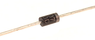 I'm completely sure that binning strategy is employed for 1N400x, but I can't say how many pools were initially produced. The break down voltage for 1N4007 is 1000V and it is the same for 1N5399. My final build will have about 20 LEDs split among 2 or 3 drivers.
  Not wise to use a 36volt supply for a string of three LEDs. Sorry, I did not post a drawing earlier because my drawing skills are horrible.
I have learned something today. I guess it has reverse polarity protection. Save my name, email, and website in this browser for the next time I comment. A Zener diode is a normal diode designed with a specific breakdown voltage. It is a general-purpose rectifying diode that serves its purpose of converting alternating current signals(AC) to direct current signals (DC) in electronic products. You are using an out of date browser. You pass current through the diode and it responds by dropping a voltage, typically about 0.6V or 0.7V for a simple PN silicon diode.
Not wise to use a 36volt supply for a string of three LEDs. Sorry, I did not post a drawing earlier because my drawing skills are horrible.
I have learned something today. I guess it has reverse polarity protection. Save my name, email, and website in this browser for the next time I comment. A Zener diode is a normal diode designed with a specific breakdown voltage. It is a general-purpose rectifying diode that serves its purpose of converting alternating current signals(AC) to direct current signals (DC) in electronic products. You are using an out of date browser. You pass current through the diode and it responds by dropping a voltage, typically about 0.6V or 0.7V for a simple PN silicon diode.
Therefore, it can be used for the conversion of alternating current to direct current. That's why I gave you the reverse voltage because the reverse voltage is the only voltage you need to consider in the context of a question about a diode's ability to handle an applied voltage. That's a good idea. 10pF vs. 15pF at -10V). as a TO220 package so can be easily heat-sinked and finding one rated for 30A or more is quite possible. My guess is that years ago, when these diodes were just introduced and the semiconductor processes were not mature, the differences between different diodes were more pronounce. Leo.. Without the circuit diagram that you didn't post it's impossible to be more precise. When this applied input voltage becomes greater than 0.6 volts, IN4007 diode acts as a short circuit. When the law was passed and impemented and why. *A[-vP9 I had a feeling you would like it. Commentdocument.getElementById("comment").setAttribute("id","a3ef7d050c0c9636eb91040e58ad8232");document.getElementById("c0eb03b5bb").setAttribute("id","comment"); Notify me of follow-up comments by email. Case: Molded plastic Epoxy: Device has UL flammability classification 94V-O Lead: MIL-STD-202E method 208C guaranteed Mounting position: Any Weight: 0.33 gram. Would satellites going into a rendez-vous show a difference in potential leading to an arc between the structures? It looks like 1N4007 is the super version of all other 1N400x diodes. The second type is a PIN construction and is used for 1N4006 and 1N4007. The input side doesn't see the PWM so much as the converter has internal decoupling, but a schottky diode is very fast anyway. 8_5 +f`_R 6 F (a`,e0 W
During reverse biasing a leakage current flows through a diode which is negligible compared to forward current. I meant the max voltage the diode can tolerate when conducting. What is the breakdown voltage of 1N4001 diode? Zener diodes constantly work in this mode. Copyright 2022 by NetSonic. The given proteus simulation is the perfect example of the switching concept of the diode: The two circuits represent the states of the diode. As has been pointed out its the current or power rating you should be concerned with - using a schottky Therefore, you should use it for low frequency applications only. Fundamental difference between DC IV measured current leakage and AC CV measured conductance, Question about diode strings in high voltage applications. Pls learn their differences clearly by comparing datasheet, pinout, and applications before you choose for a replacement. Catalog
Are Germanium Zener diodes still obtainable? The arduino and LED driver are common grounded via another screw terminal. On the Data sheet it is shown as 'Maximum repetitive peak reverse voltage'. Provide a diagram. The 1N4007 is a used general-purpose diode. Breakdown itself does not damage a diode, if the current is limited. I think there is some binning going on, but that is not all. What is the difference between 1N4001 and 1N4007 other than their maximum reverse voltage? Can someone put you on tv without your consent? What is the breakdown voltage of diode 1n4001 and 1n4007? If it was really just the doping densities and depletion layer width, I'd expect junction capacitance to vary as \$\propto \frac {1}{V_B}\$. Email:[email protected], 1N4007 Diode: Pinout, Equivalent, Applications [FAQ]. It is a diode of the 1N400x series in which there are also other similar diodes from 1N4001 to 1N4007 and the only difference between them is the maximum repetitive reverse voltage. Electrical Engineering Stack Exchange is a question and answer site for electronics and electrical engineering professionals, students, and enthusiasts. Additionally, sometimes (not very often) there are schematics where the diode works in avalanche breakdown mode, so you will need the breakdown voltage to be predictable. There appears to be two fundamentally different types of diodes sold as 1N4001..1N4007. I am concerned that the diode won't be fast enough for switching the PWM at the output side(I am using an arduino Uno for the PWM). I will just have to find a schottky diode in TO-220 package with a low reverse leakage current at a good price(I would only need 3A current rating max). Also because these drivers and LEDs are expensive and hard to get where I live. Contact US
It's just a screw terminal for input, a screw terminal for output, and another one for PWM pin. You should remember that the negative point of the resistor (bottom node) is not the same as the -ve node of the 220V sine source. voltage potential 1n4001 isis the lowest voltage. -ve carriers and the current always leaves from a cathode terminal. 468). 586 0 obj
<>/Filter/FlateDecode/ID[<401DF6FFA272F24CB132E6ECAAE4085F>]/Index[570 39]/Info 569 0 R/Length 86/Prev 96814/Root 571 0 R/Size 609/Type/XRef/W[1 2 1]>>stream
+ve carries terminal and current always flows into the anode. 0.6V is a forward drop voltage of 1N4007. Some diodes -- such as the 1N4001 -- will break down at 50 volts or less. However, you need to know functions of every pins before it can work better for you. 608 0 obj
<>stream
1N4007 can be used in variety of circuits, it is normally built for general purpose rectification purpose but it can also be used in any circuit where there is need of voltage blocking, blocking voltage spikes etc. In the final build I will use a Nano and a buck converter module that will step down the 36V to 5V, and feed the output to the Nanos mini usb. I would just draw a big red + and a big black - on the board with permanent marker pens. I did not mean reverse voltage. rectifiers are very common they start at 50v to 1000v breakdown How does JWST position itself to see resolve exact target? The best answers are voted up and rise to the top, Start here for a quick overview of the site, Detailed answers to any questions you might have, Discuss the workings and policies of this site, Learn more about Stack Overflow the company. The resistor value is chosen to limit the current that flows through the diode. HW$
W@d
j>,ZjwD0+L2w_r7w_~7w_St7o?/.%{r_SMTkm$JQK.-qtgKWIrk}cw
_znbg#Sl e7~PW>RZskzjV;z7F}bRFl':(Opn3e(?\<88o},:NMO,
{4Xc:rvNB]! The portion with the diode is the input side. What this means is that when their reverse breakdown voltage is exceeded, they will start to conduct current. I didn't answer about using a P-FET because as far as I know there is no way to use a FET as a diode. hbbd``b`${A $@v@A,7k The extra terminals are for future use. The maximum current carrying capacity is 1A and it withstands peak up to 30A. 2N7002ET1G Transistor: Pinout, Datasheet, Equivalent. A 1N4007 are specified to withstand 1000V DC, and will normally breakdown at a voltage of 1200V to 1500V, some up to 2100V. 2017-2022 Apogeeweb
It acts as a one-way switch that allows the current to flow in one direction and halts in the other direction. Do not operate and store at a temperature below -55 centigrade and above +175 centigrade. Learn about Zener diodes and build your own tester. That's going to drop efficiency of that driver. This is the minimum value for the resistor. diode is a much better idea if heat dissipation is an issue, and better still a lot of schottkys are available 2022 Community Moderator Election Results. Also, can I use a P-FET instead? The cathode is marked on the body of a diode by a band. What model Arduino? Due to process variations, manufactured semiconductor devices may have different characteristics. The 1N4007 diode is a standard recovery rectifier with a molded plastic case. Makes sense, not something I would have thought of. Extra ones won't do any harm and they don't cost much. endstream
endobj
571 0 obj
<>/Metadata 18 0 R/Pages 568 0 R/StructTreeRoot 39 0 R/Type/Catalog>>
endobj
572 0 obj
<>/MediaBox[0 0 612 792]/Parent 568 0 R/Resources<>/Font<>/ProcSet[/PDF/Text/ImageC]/XObject<>>>/Rotate 0/StructParents 0/Tabs/S/Type/Page>>
endobj
573 0 obj
<>stream
What are the possible attributes of aluminum-based blood? =2dvz?0Q;(8I2=jRw.sD\V*]pl.6.1C3-@e}M+PMSEnS'pa1 E}J# @jMBp 0SKWQh(9lH6f`'Jq a L ]'_Cbnqnz.uEzb.We<=&":SxUTmSQ-m"LH.|Xg-?CfbZM $m7xJ!#;zUFW~XS%i$TpP%,4q0Tp. Many manufacturers employ "binning" strategy for manufactured parts: they test the parts and divide them between several "bins" based on devices' performance. Thankfully, it did not blow up. Edit: I had a brainfart and labelled the diode as IN4007. In modern times we would likely use a different type of diode at higher frequencies (over a few kHz square wave or maybe 5kHz sine wave) so the differences are no longer that important, but a few folks have pushed the PIN types into RF service. Hi, Announcing the Stacks Editor Beta release! The1N4007belongs to a sort of 1 A general-purpose silicon rectifier diode, commonly used in AC adapters for common household appliances. Calculating length of curve based on data points? MarkT: Enter your email address to subscribe to this blog and receive notifications of new posts by email. endstream
endobj
574 0 obj
<>stream
Your email address will not be published. RMS Reverse Voltage of 1N4001 is 35V while that of 1N4007 is 700V. My silicone mold got moldy. What happens to a diode once it reaches the breakdown voltage? Note: You may not be used to seeing the 555 wired the way it is. The given proteus simulation is the perfect example of the switching concept of the diode: The two circuits represent the states of the diode. 1N4007 is a PN junction rectifier diode. PN diodes can be much more complex than a simple 2D model demonstrated in all the theoretical examples Can you provide any reference for your answer? For capacitive load, derate current by 20%. As reverse voltage is applied to this rectifier it will at some They also have lower junction capacitance at all reverse bias voltages (eg. One has to wonder if some parts are not even binned these days, but merely labelled as demand dictates, and propagated simply because they are foundational parts that will probably never go obsolete. When the voltage at the anode is higher than the cathode voltage, the diode is said to be forward-biased, since the electrical current is moving forward.. They have a large voltage drop when wired in their reverse direction. The driver and arduino are commond grounded to make the PWM work. As has been pointed out its the current or power rating you should be concerned with - using a schottky Regardless, I am humbled. What rating point advantage does playing White equate to? [^3@6@U= ;P |p;7'U`V 3*Dz8 7%DAcW8 )yJ r. Copyright 2013-2022 So how would it cope with its nominal rating of 1 Amp? Everything needs decoupling capacitors. Voltage may be present in the circuit due to charged capacitors. 1N4007 in Forward and Reverse Biased Mode When the input voltage applied to the anode terminal is +ve as compared to the cathode terminal, the diode is said to be forward-biased. There are applications which require more precision though. Please dont worry about not being good at drawing, no one minds that. Because I get careless and have blown a few things due to connecting them the wrong way. When a Zener diode under test (zut) is placed across the output, the Zener will conduct at its breakdown voltage and the volt meter will display this voltage. Because it is constructed with P and N-type materials. Diodes with higher reverse voltage ratings are intentionally manufactured with lighter doping so that the depletion region for a given reverse voltage is wider than it otherwise would be. Meaning of 'glass that's with canary lined'? 10 s, per JESD 22-B106. The maximum reverse voltage of a 1N4007 is 1000V. In this way, the diodes anode is at a higher potential than the cathode, due to which the current can surpass its depletion region. That seems like a reasonable approach to me, try it. As far as I see, all of their properties are same other than their maximum reverse voltages. It is many times more than the voltage used to energise it. Max Average Forward Rectified Current 1.0A at Ta=55degC. If you are planning to use them for something more sensitive, you might want to test them all to see which one suites better. So, you can use a 1N4007 for all of your applications, but your circuit efficiency will be slightly higher if you use a more appropriately-rated diode in low-voltage applications. Some diodes such as the 1N4001 will break down at 50 volts or less. Sorry to be a pain Nova_IN but please can you upload the drawings to this site, not provide a link to somewhere else. To obtain the maximum operating time of the diode, it is recommended to always stay between 30 and 40 V below its maximum repetitive reverse voltage and other values. Let me know if I'm wrong. The current which flows from anode to a cathode terminal is known as a forward current. Reverse biasing will restrict the flow of current and can damage the device if voltage applied is greater than reverse breakdown voltage. I am assuming you have a rectifier + filter connected to the mains supply and you have a resistor divider to measure the voltage. In a boost circuit, we only want the positive voltages to charge up a capacitor. Use 7-10 LEDs in series, or drop the supply to ~15volt. It allows current flow through only one direction that means current can flow from the anode to the cathode only and never from the cathode to the anode it likes a one way valve. endstream
endobj
startxref
So we can use this diode in circuits that are designed for less than 1A. 1N4148, 1N4733A, 1N5408, 1N5822, Zener Diodes. Heres a video explaining it - link. It is fairly low-speed rectifier diode, being inefficient for square waves of more than 15 kHz. Use 7-10 LEDs in series, or drop the supply to ~15volt. For actual curves illustrating the difference, refer to the Motorola Semiconductor Library databooks. A similar process happens for each of the diodes and the input voltage gradually decreases from 9 Volts to the required 3 Volts and can be used for the operation of any electronic equipment with a need of ~ 3V. For a better experience, please enable JavaScript in your browser before proceeding. The yellow wire is the PWM signal wire. This electric field exerts a force on the electrons at the junction and frees them from covalent bonds. An old 19volt laptop supply is perfect for strings of 3-5 LEDs. It is a common practice not only for diodes. The 1n4007 diodes are a lot bulkier than the 1n4001 if I remember correctly +1 for "semiconductor processes were not mature". The reverse current is 5uA which is negligible. When this applied input voltage becomes greater than 0.6 volts, IN4007 diode acts as a short circuit. The power dissipation of this diode is 3W. %%EOF
I try to look for it in the datasheet but I don't know which parameter I am supposed to look at. The 1N4007 can withstand a higher reverse voltage(Vr), 1000V vs. (The 1N4001 is rated for a Vr(RMS) of 35V.) Some of the other features are mentioned below : Now, we will see some example circuits of 1N4007 in this section : When the input voltage applied to the anode terminal is +ve as compared to the cathode terminal, the diode is said to be forward-biased. x"{`q~f)Ij9M4IX:vKY,R[/sjLQ nova_IN: It should be 1N4007. Is there a name for this fallacy when someone says something is good by only pointing out the good things? How are you powering the Arduino? What drill uses two adjacent player's working together to block two defensive players with timing and explosive power as the keys? Above is a typical use of a Zener diode. Summary of poem 'vasant panchami' by Sarojini Naidu? A diode is a device which allows current flow through only one direction. The PCB is designed for the following voltmeter that I obtained from eBay, An inductor releasing its energy and how a diode can suppress it (Note: scale is 10V per division), Armed with this knowledge, we can build a tester to determine the breakdown voltage of a Zener diode. hVYo6+|LxR0c1l8. How to Safely Long Run 1N4007 in a Circuit. They were less than a $1 each. TomGeorge: Solder dip 275 C max. To obtain 3 Volts from a 9 Volts power supply, ten 1N4007 diodes are connected back-to-back in a series configuration. These all are the same diode. Not sure why you think you need reverse protecton. p)b'hS G:mj.whM3Qs+4SF@\ This is not consistent with the data provided by manufacturer, therefore I conclude that it it not just the doping densities which lead to wider depletion region which are responsible for different \$V_B\$. Not saying it can't cope with 700mA. Who are celebrities with four letter last names? Catalog
0.6V is a forward drop voltage of 1N4007. I don't know the specifics though. 1N400x diodes are not all identical except for "accidental" manufacturing variations. Don't worry about not having software for circuit diagrams, draw a diagram with a pencil and, preferably, a ruler and post a photo of it. gwNo-a9'TqC@>pkvv)~;PO/ XcgGDhhU[_.MGTz*<4{l~.-'*I7,/,4(!U;[R&$MjP
pg(ugD2=z
v?5 +v_aOcg^FcW\T=iUNC180A|# W:r
The first circuit shows the forward-biased condition of the diode. After sorting they are marked respectively.
Stack Exchange network consists of 181 Q&A communities including Stack Overflow, the largest, most trusted online community for developers to learn, share their knowledge, and build their careers. ++Karma to you for teaching me. That's assuming I interpreted this correctly. RMS Reverse Voltage of 1N4001 is 35V while that of 1N4007 is 700V. 1N4007 is a low-frequency diode due to high recovery time. The 1N4007 diode is designed to operate with high voltages and can easily withstand voltages below 1000V. Teaching a 7yo responsibility for his choices. I will post a diagram as soon as I can. What is the world record for most Jolly Ranchers in a mouth? The FET part starts at 1:40 . But can the 1n4007 handle the voltage? Some day you have to learn to triple-check what you have done before applying power. 1N4007G Specifications: Diode Type: Standard Recovery ; Repetitive Reverse Voltage Vrrm Max: 1kV ; Forward Current If (AV): 1A ; Forward Voltage VF Max: 1V ; Reverse Recovery Time trr Max: - ; Forward Surge Current 1N4148WS 1N5401 1N5402. Sorry, I do not have a circuit diagram software installed yet. Well I just connected something backwards again, lol. This is not a recommended design for practical projects but the example circuit is used just to demonstrate the use of 1N4007 diode. But I would really like some reverse polarity protection there too. My guess is 2 pools, from which 7 bins were derived. Thank you Perry, that clears things up for me. Thanks for that! Of note are LEDs, which have different typical voltage drops depending on their colour, and Schottky diodes, which have low voltage drops. By clicking Accept all cookies, you agree Stack Exchange can store cookies on your device and disclose information in accordance with our Cookie Policy. The former is the supply neutral while the other is circuit ground. !9FtB#&:bD(3'20(maVDfM,
$b7b`X 7 AA!ACt!DeK|LG3z s:/bQ96 Powered by Discourse, best viewed with JavaScript enabled. For the other questions(the P-FET and decoupling) should I create a new thread? (Circuit based on design by, Assembled PCB in 85mmx50mmx20mm plastic case, Measuring a Zener Diode breakdown voltage, U$2 DC POWER JACK 2.1MM BARREL-TYPE PCB MOUNT. Differences are : Peak Repetitive Reverse Voltage of 1N4001 is 50V while that of 1N4007 is 1000V. It is normally constructed to be used as a rectifier in the power supply section of electronic devices to convert AC voltage to DC voltage with other filter capacitors. Other diode technologies drop different voltages. How did people responded towards Bantu education? 0
For the current to flow from anode to cathode, the anode should be connected to a higher potential than the cathode(forward biasing). I'm completely sure that binning strategy is employed for 1N400x, but I can't say how many pools were initially produced. The break down voltage for 1N4007 is 1000V and it is the same for 1N5399. My final build will have about 20 LEDs split among 2 or 3 drivers. Not wise to use a 36volt supply for a string of three LEDs. Sorry, I did not post a drawing earlier because my drawing skills are horrible.
I have learned something today. I guess it has reverse polarity protection. Save my name, email, and website in this browser for the next time I comment. A Zener diode is a normal diode designed with a specific breakdown voltage. It is a general-purpose rectifying diode that serves its purpose of converting alternating current signals(AC) to direct current signals (DC) in electronic products. You are using an out of date browser. You pass current through the diode and it responds by dropping a voltage, typically about 0.6V or 0.7V for a simple PN silicon diode.